Concept Car Geometry Development and CFD Pipeline Implementation
Domain: Automotive Design and Aerodynamics
Tools: Blender, snappyHexMesh, OpenFOAM, ParaView, gnuplot, 3D Printing
Project Type: Self-driven follow-up project
Status: Phase 1 complete — digital-to-physical workflow established; CFD pipeline converged
GitHub Repository:
👉 https://github.com/tjaditya/cfd-car-geometry
Project Context
This is a self-driven follow-up project to a 3-week onsite summer course in “Introduction to Car Design” at Istituto Europeo di Design (IED), Turin.
The objective was to take an early-stage concept design and develop it into:
- a CFD-ready 3D geometry suitable for airflow analysis, and
- a complete open-source CFD workflow that can be repeated and improved through iteration.
In addition to the digital pipeline, I 3D printed the geometry, incorporated faculty feedback, and produced a modified second iteration. This phase focused on establishing a robust, repeatable baseline workflow, rather than optimizing aerodynamic performance.
Concept and Early Form Exploration
The initial phase focused on exploring overall proportions, stance, and surface flow in Blender.
Key areas of attention:
- wheel arch placement
- frontal intake shaping
- roof curvature and rear taper
At this stage, the emphasis was on form exploration without constraining the design too early based on simulation limitations.
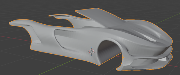
Early concept-stage form exploration in Blender, focusing on proportions, stance, and overall surface flow before applying simulation constraints.
Full Body Surface Development
The concept was progressively refined into a continuous full-body shell.
Key refinements included:
- smoothing abrupt curvature transitions
- improving surface continuity across major panels
- eliminating visually appealing but non-physical sharp edges
These changes were made with the understanding that surface quality directly impacts CFD mesh stability and solver robustness.
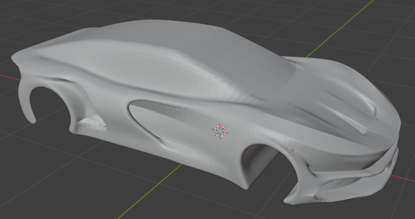
Progressive refinement into a continuous body shell, improving curvature continuity and eliminating sharp, non-physical transitions.
Topology and Mesh-Aware Modeling
Once the overall form was established, the model was reworked with mesh awareness in mind.
Steps taken:
- clean and consistent topology aligned with surface curvature
- removal of non-manifold edges
- reduction of unnecessary geometric complexity
- preparation for watertight surface export
This phase was critical in bridging the gap between design-oriented modeling and engineering simulation.
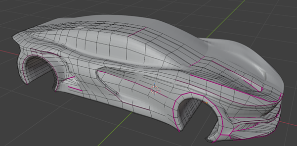
Topology cleanup and edge-flow alignment performed with mesh stability and CFD suitability in mind.
Interactive Geometry
The interactive model below shows the external body geometry used for CFD analysis and physical prototyping. It is intended to highlight surface continuity and curvature transitions before meshing and simulation.
Tip: drag to rotate, scroll to zoom.
Physical Prototyping and Feedback-Driven Iteration (3D Printing)
To complement the digital workflow, I 3D printed the car model through an external vendor to validate proportions, surface continuity, and manufacturability.
After reviewing the first print, I received feedback from an IED faculty mentor related to surface coherence and overall form.
Based on that feedback, I modified the 3D geometry and produced a second iteration, which was also 3D printed. This reinforced an iterative engineering mindset where critique and physical validation inform the next design version.
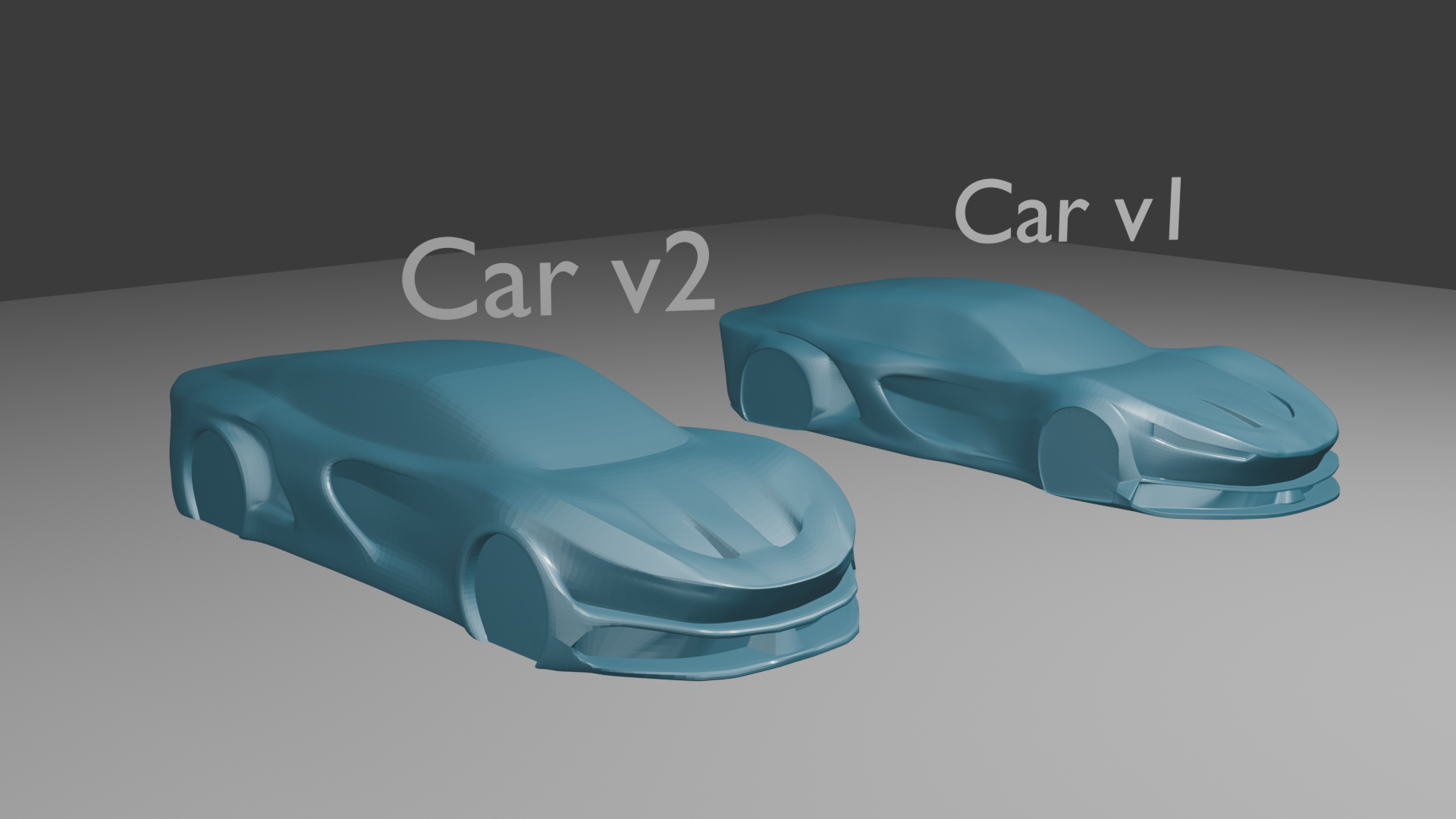
Comparison of the models from the 2 iterations
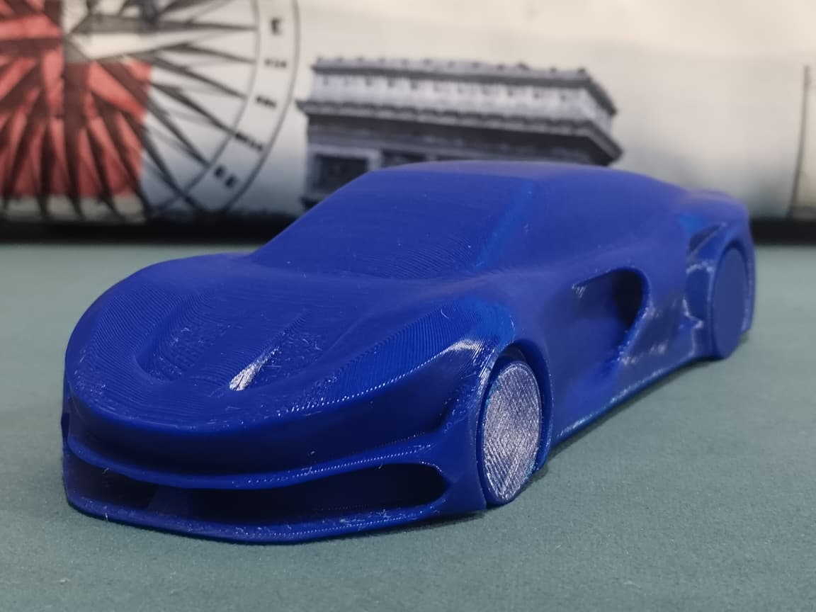
3D print of version 2 used for CFD
CFD Pipeline Overview
This project extends beyond geometry preparation into a complete open-source CFD workflow for external aerodynamics.
Pipeline:
    Blender (.blend)
      -> STL export
      -> snappyHexMesh (surface and volume meshing)
      -> OpenFOAM (steady-state solver: simpleFoam)
      -> ParaView (flow visualization and analysis)
Geometry Export and Technical Pre-processing
The finalized external body shell was prepared in Blender and exported as a watertight STL for external aerodynamics analysis.
At this stage, the focus was on producing a clean, simulation-ready geometry rather than a visually complete vehicle model. The geometry represents an abstracted aerodynamic body suitable for stable meshing and solver convergence.
Key pre-processing decisions:
- ensuring a fully closed, watertight external surface suitable for volume meshing
- verification and correction of surface normal orientation across the entire body
- removal of fine decorative features that do not meaningfully influence external flow
- removal of wheels and ground plane to simplify the problem and isolate body-driven flow effects
- simplification of underbody geometry to avoid unnecessary meshing complexity
- alignment of the geometry with the global coordinate system for consistent CFD domain setup
By excluding wheels and ground interaction at this phase, the simulation remains computationally tractable and well-suited for studying baseline flow behavior, separation, and wake structure around the body.
Final External Body Shell (CFD-ready)
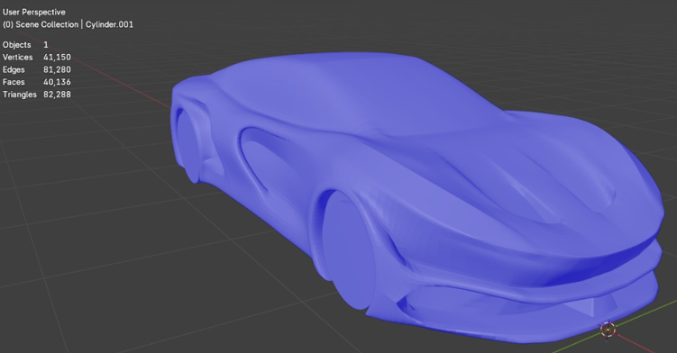
Final external body geometry after cleanup and simplification. Wheels and ground plane have been removed to isolate the aerodynamic influence of the body shape.
Surface Closure and Normal Orientation Verification
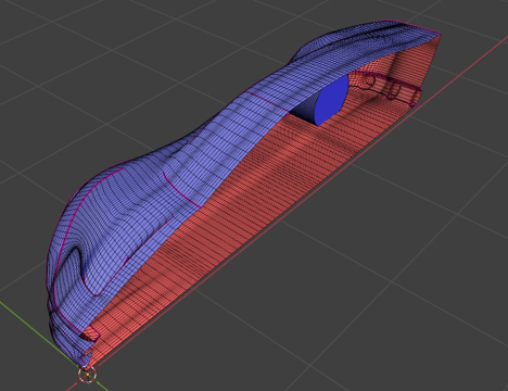
Inspection of the closed external body shell in Blender with face normal visualization enabled. Surface normals were checked and corrected to ensure consistent outward orientation, preventing meshing and solver instability.
CFD Meshing Strategy (snappyHexMesh)
Surface and volume meshes were generated using snappyHexMesh, selected for its ability to produce hex-dominant unstructured meshes around complex external geometries within an open-source CFD workflow.
The meshing strategy focused on:
- capturing global body curvature without excessive cell counts
- applying local refinement in aerodynamically sensitive regions (front fascia, roof, rear wake)
- maintaining mesh quality suitable for steady-state solvers
Rather than uniformly refining the entire domain, refinement regions were applied selectively. This reflects how CFD is used in early-stage aerodynamic exploration—balancing physical resolution, numerical stability, and computational efficiency.
At this stage, the objective was not high-fidelity force prediction, but the generation of a stable mesh capable of resolving major flow features and wake behavior.
Mesh Quality Verification
Mesh quality was evaluated prior to simulation to ensure numerical robustness and solver stability.
Quality checks included:
- non-orthogonality
- skewness
- cell aspect ratios
The mesh met quality requirements for steady-state external aerodynamics with simpleFoam. Although not designed for accurate force prediction, it was sufficient for qualitative analysis of flow separation and wake structure, as verified through OpenFOAM mesh quality diagnostics.
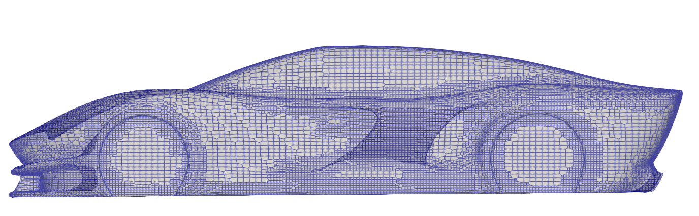
Surface mesh visualization highlighting local refinements
Steady-State Flow Simulation Setup (OpenFOAM)
Flow simulations were performed using OpenFOAM with the simpleFoam solver, appropriate for steady-state, incompressible external aerodynamics.
Key setup elements included:
- uniform inlet velocity representing freestream conditions
- no-slip boundary condition on the vehicle surface
- fixed pressure outlet boundary condition
- turbulence modeling suitable for steady external flow studies
The objective of this phase was to establish a stable and converged solver configuration capable of producing physically interpretable flow fields, rather than absolute aerodynamic performance metrics.
Model Validation & Iteration
During early post-processing, I observed flow features that appeared physically inconsistent despite solver convergence and identified that the vehicle orientation in the Blender model was reversed relative to the intended inlet flow direction. I corrected the model orientation, regenerated the mesh, and restarted the simulations, using the revised setup for all subsequent analysis, reinforcing the importance of validating geometric assumptions and boundary conditions rather than relying solely on numerical convergence.
CFD Results and Convergence Validation
The steady-state solution converged after approximately 2000 SIMPLE iterations.
Convergence was assessed using:
- residual reduction for governing equations
- stabilization of integrated force coefficients over successive iterations
Both criteria were used together to distinguish numerical convergence from physically meaningful stabilization. This reinforced the understanding that residual decay alone is not sufficient to assess solution reliability.
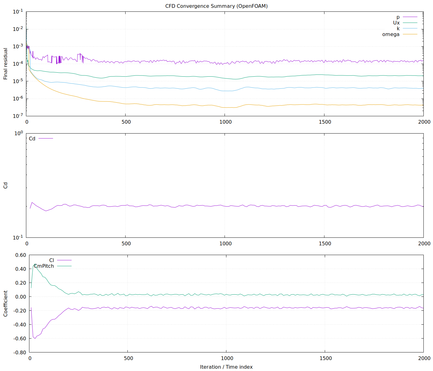
Residual histories and force coefficient trends were extracted from OpenFOAM logs and plotted using gnuplot, confirming numerical convergence and stabilization of the steady-state solution.
Flow Visualization and Qualitative Analysis (ParaView)
With a converged steady-state solution obtained, ParaView was used to perform qualitative flow analysis aimed at understanding three-dimensional flow behavior around the body.
Post-processing focused on:
- normalized velocity (U/U∞) contours to examine flow acceleration and deceleration over key surfaces
- normalized velocity slices (U/U∞) at multiple heights to study vertical variation in the flow field
- streamline and streamtracer visualization to examine wake formation and recirculation behavior
Rather than relying on a single visualization, multiple complementary views were used to build a physically consistent picture of the external flow.
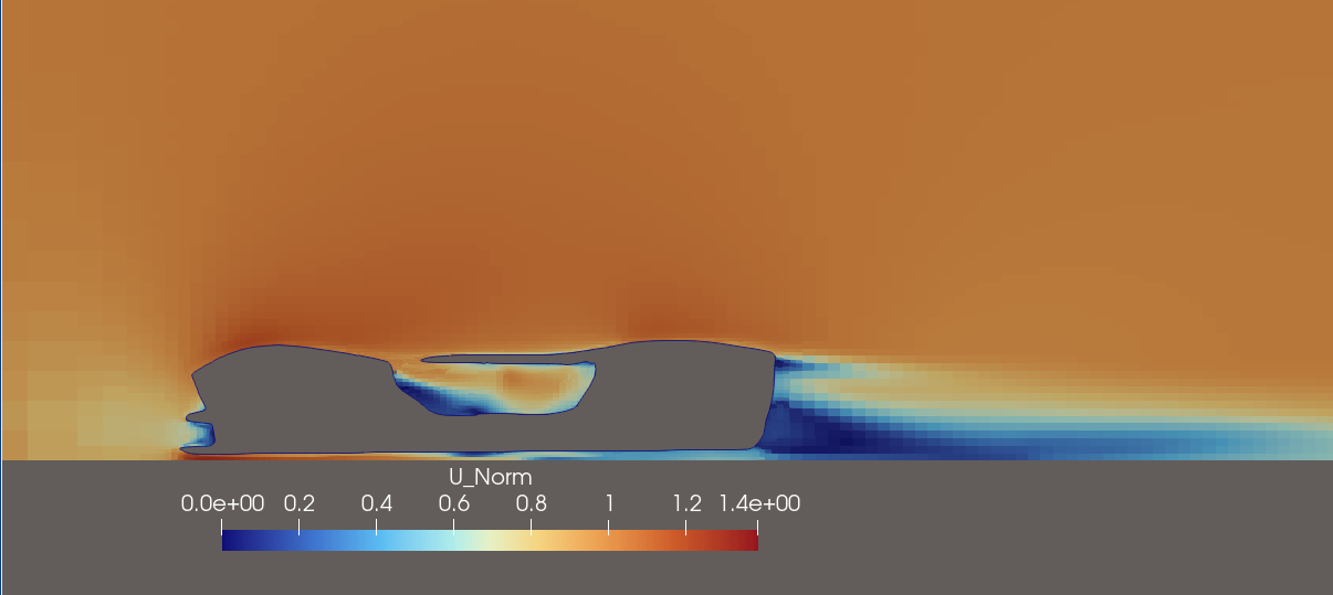
Velocity Distribution Across Vertical Sections
Normalized velocity slices (U/U∞) were extracted at three representative vertical planes—near the ground (underbody), at mid-height, and above the roof—to examine how flow behavior varies across the height of the body.
The roof-level slice lies largely outside the near-body flow and is dominated by freestream conditions. Only a thin, elongated velocity deficit is observed downstream, indicating the upper extent of the wake and confirming that the primary wake structure remains confined closer to the body.
At mid-height, the influence of the vehicle geometry is more pronounced. This slice captures the core wake region, with reduced velocities extending downstream of the rear surfaces. It highlights the primary separation behavior and lateral spreading of the wake driven by the overall body shape.
The underbody slice exhibits the strongest velocity variations. Local acceleration is observed as the flow passes through the constricted region beneath the body, followed by a broader velocity deficit downstream. These features reflect the combined influence of surface proximity, simplified underbody geometry, and flow expansion into the wake.
Together, these slices illustrate the vertical stratification of the external flow field: freestream-dominated behavior above the body, wake-dominated flow at mid-height, and accelerated, geometry-influenced flow near the underbody. This comparison reinforces the role of overall body curvature and rear geometry in governing wake formation and recovery.

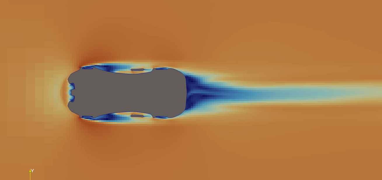
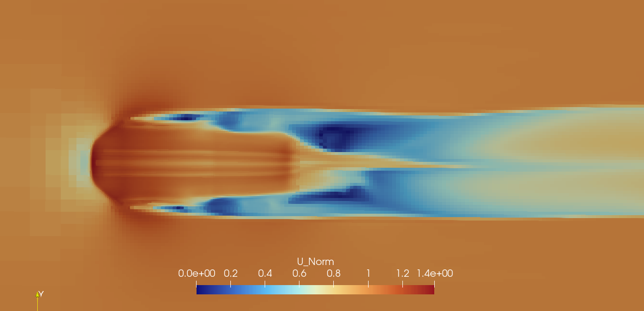
Normalized velocity contours at roof, mid-height, and underbody sections, illustrating vertical variation in flow behavior and wake development.
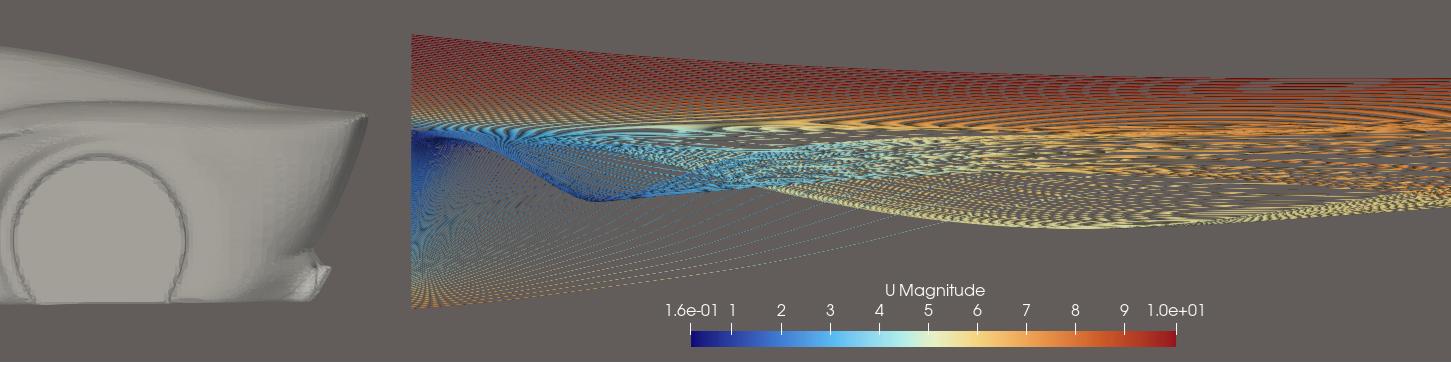
Mid-Plane and Side Periphery Flow Behavior
Additional velocity slices were extracted along the vehicle centerline and through the side periphery, intersecting the wing-like structural elements that emerge from the body, curve outward, and rejoin downstream as a continuous hoop-like form.
These sections were chosen to examine how localized three-dimensional geometry influences flow acceleration, deviation, and interaction with the surrounding flow field. The mid-plane slice provides a reference view of overall flow attachment and separation along the primary flow direction, while the periphery slice captures the effect of the wing–hoop structure on local velocity distribution and flow redirection.
The periphery slice highlights regions of localized acceleration and flow curvature induced by the side-mounted feature, illustrating how such geometry introduces three-dimensional effects even in an otherwise symmetric external flow. Together, these views emphasize how secondary design elements can influence local flow behavior without dominating overall wake structure.
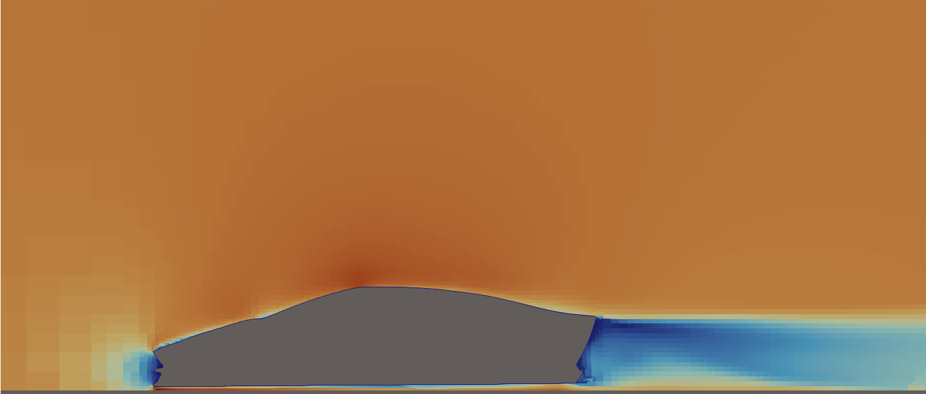
Normalized velocity (U/U∞) slices through the vehicle mid-plane and side periphery, illustrating localized flow behavior influenced by the wing–hoop structural geometry.
Wake Structure and Streamtracer Visualization
To interpret wake formation and downstream flow behavior, streamtracer visualization was used with seeds placed just downstream of the rear geometry and integrated in the freestream direction.
The resulting streamtracers reveal a low-velocity wake region immediately behind the vehicle, followed by gradual recovery toward freestream conditions farther downstream. Compared to scalar velocity contours alone, this representation provides clearer insight into wake extent, lateral spread, and overall coherence.
Consistent with the steady-state RANS formulation and simplified boundary conditions used in this phase, the wake appears smooth and coherent and is interpreted qualitatively rather than as a representation of unsteady turbulence.
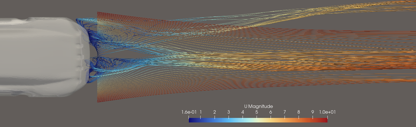
Streamtracer visualization illustrating wake separation and downstream recovery behind the vehicle.
Surface Pressure Distribution and Wake Correlation
Surface pressure distribution on the vehicle body was examined to support interpretation of the velocity and wake results.
Higher pressure regions are observed on the frontal surfaces, while lower pressure dominates toward the rear of the body. The rear pressure deficit is consistent with flow separation and wake formation identified in the velocity slice and streamtracer visualizations.
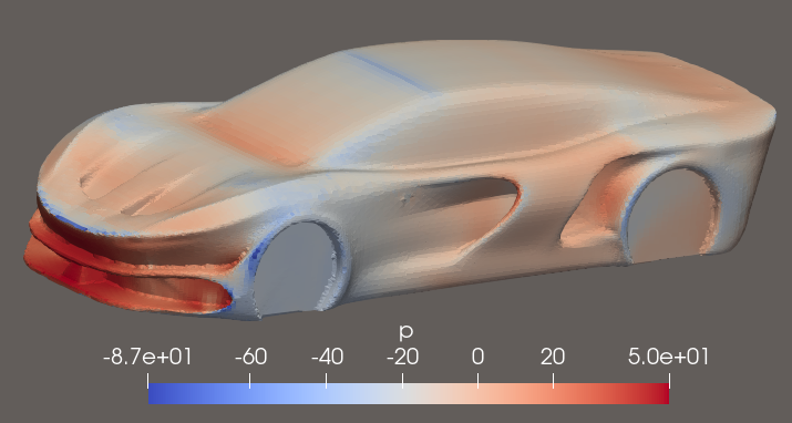
Surface pressure distribution showing frontal pressure buildup and a rear low-pressure region associated with wake formation. This visualization is used for qualitative interpretation rather than quantitative force estimation.
Interpretation and Engineering Insights
This project shows how design intent, geometric quality, and CFD analysis come together in early-stage aerodynamic studies.
The CFD results indicate mostly attached flow over the hood and roof, reflecting the smooth surface transitions achieved during geometry refinement. In contrast, the rear geometry drives wake formation, with flow separation producing a clear velocity deficit and low-pressure region downstream. These patterns appear consistently across normalized velocity slices, streamtracer visualizations, and surface pressure plots.
Vertical velocity comparisons show that wake effects are strongest near the body and underbody, while the flow above the roof remains largely freestream-dominated. Mid-plane and peripheral slices further show how secondary geometric features introduce localized three-dimensional effects without changing the overall wake structure. Together, these results highlight the importance of overall body shape and rear taper in controlling separation and wake recovery.
From an engineering standpoint, this phase reinforced several important points:
- clean, watertight geometry is required for stable meshing and solver convergence
- mesh refinement choices determine which flow features can be interpreted reliably
- numerical convergence alone does not guarantee physical accuracy
- CFD is best used as a comparative and exploratory tool at early design stages
Overall, the project establishes a repeatable, open-source workflow linking concept design, physical prototyping, and qualitative aerodynamic analysis. This provides a solid foundation for systematic geometry iteration and more detailed studies in future phases.
Next Technical Focus
With the CFD pipeline established and validated, active development on this project is now paused. Current efforts are focused on a Raspberry Pi–based autonomous rover platform centered on the simulation, validation, and deployment of Advanced Driver Assistance Systems (ADAS) concepts.
The CFD pipeline developed here remains available as a reusable framework for future design studies or comparative aerodynamic analysis, should the need arise.
Potential Extensions
- Comparative study with the modified model
- Extraction of basic aerodynamic coefficients for relative comparison
- Controlled geometry variations to study qualitative aerodynamic trends
These extensions are noted for completeness but were intentionally excluded from the current scope.